Note: these abbreviations are from the GM workshop manual but are fairly common for most makes and models. Describe what they mean below.
PCM: Power-Train Control Module.
The Power-Train Control Module is a combined control unit, consisting of the Engine Management ECU and the Transmission Control Unit
TCC: Torque Converter Clutch
The Torque Converter Clutch acts as the equivalent of a manual clutch. It separates the load from the power source
TPS: Throttle Position Sensor
The Throttle Position Sensor or TPS is a sensor that monitors the position of the throttle in an internal combustion engine
ECT: Engine Coolant Temperature
The Engine Coolant Temperature is a sensor that turns on the electric fan or sends a signal to the operator when the coolant reaches a temperature above it's recommended parameters
VSS: Vehicle Speed Sensor
Detects how fast the wheel is rotating by using a rotor tooth and sensor that sends a signal to the ECU
PSA: Transmission Range Fluid Pressure Switch Assembly
The PSA is a sensor that detects all the shift points in the shifting of the gears in an Automatic Transmission
TTS: Transmission Temperature Sensor
The TTS lets the ECU know how warm or cold the transmission fluid is and adjusts the timing of the shifts.
Monday, August 23, 2010

Using a Scan Tool
Using a scan tool, go to the ABS live data screen and note all the sensors, data and what it's telling you
1. A/con Switch Off
2. BPP Off
3.Power Steering Pressure Off
4. MT/AT discrimination Off
5. Neutral/ Clutch Switch On
6. Refridgerant Press Switch Off
7. Trans Range (DLC) On
8. Ten Terminal (DLC) On
9. Cooling Fan Control (Hi) Off
Using the scan tool on the vehicle you have been assigned to. Go to the actuator test screen. Note below what component you have tested and what happened when you tested that component and the test results.
1. # of Continuous DTCS in modulator 3
2. ABS Valve CTRL Relay on
3. ABS warning lamp status off
4. BAT positive volt 14.69
5. Brake Switch In off
6. Hydraulic Pump Motor x2 off
7. LF ABS inlet valve off
8. LF ABS output valve off
9. LF Wheel Speed Sensor 0kmh
10. RF ABS inlet valve off
1. A/con Switch Off
2. BPP Off
3.Power Steering Pressure Off
4. MT/AT discrimination Off
5. Neutral/ Clutch Switch On
6. Refridgerant Press Switch Off
7. Trans Range (DLC) On
8. Ten Terminal (DLC) On
9. Cooling Fan Control (Hi) Off
Using the scan tool on the vehicle you have been assigned to. Go to the actuator test screen. Note below what component you have tested and what happened when you tested that component and the test results.
1. # of Continuous DTCS in modulator 3
2. ABS Valve CTRL Relay on
3. ABS warning lamp status off
4. BAT positive volt 14.69
5. Brake Switch In off
6. Hydraulic Pump Motor x2 off
7. LF ABS inlet valve off
8. LF ABS output valve off
9. LF Wheel Speed Sensor 0kmh
10. RF ABS inlet valve off
11. RF ABS Output Valve off
12. RL Wheel Speed Sensor 0kph
13. RR ABS output Valve off
14. RR Wheel Speed Sensor 0kph
ABS Wheel Speed Sensors
On the vehicle you have been assigned does it use analogue or digital wheel sensors?
Frequency Observations....
Analogue
How did you conclude the wheel sensors were analogue or digital?
How did you conclude the wheel sensors were analogue or digital?
Because there are only 2 wires on the sensors. Digital sensors have three.
Measure the air gap for each sensor. State the air gap and visual condition of each wheel sensor.
Front Right
.838. The air gap was good, the gap should be between .4 and 1mm
Front Left
.838. The air gap is good. The gap is between the specifications, and there is no visual wear to the sensor.
Rear Right
Rear Right
1.043. The air gap is off and needs to be adjusted. No evidence of wear
Rear Left
Rear Left
1.043. The air gap is off and needs to be adjusted. No evidence of wear.
Using an oscilloscope connect it to a wheel sensor and record the pattern shown, If the sensor is a analogue sensor then just connect the probe and spin the wheel. If the sensor is digital you will need to have the ignition before you turn the wheels. (Left Image Front Wheel Sensor), (Right Image Rear Wheel Sensor)
Using an oscilloscope connect it to a wheel sensor and record the pattern shown, If the sensor is a analogue sensor then just connect the probe and spin the wheel. If the sensor is digital you will need to have the ignition before you turn the wheels. (Left Image Front Wheel Sensor), (Right Image Rear Wheel Sensor)


Is this pattern analogue or digital?
Analogue
Using the frequency scale on a multimeter. Turn the wheel approximately the same speed as in the above test. Note the frequency and compare it to the graph you drew above.
Using the frequency scale on a multimeter. Turn the wheel approximately the same speed as in the above test. Note the frequency and compare it to the graph you drew above.
Frequency Observations....
My recorded results when measuring the frequency of the wheels with a multimeter were 2.96 and 2.97 KHz for the front wheel sensors and 3.15-3.16 KHz for the rear wheel sensors. Meaning the rear wheels were spinning slighty faster.
Sunday, August 22, 2010
Relay Waveforms
 Capture a waveform that shows both the control circuit change when it turns on the relay, and the power switching on to power something in the ABS system. (Use an oscilloscope with 2 channels to capture this pattern. You may have to carefully set the trigger to capture this.)
Record the waveform below with the time and volts per division, and explain what you're measuring.
With the ABS switched off, I measured the voltage on the system relay control circuit with one oscilloscope and recorded 0.5 volts at 86 and 0V at 30. In this case, the wiring diagram indicates that 86 and 85 being the control circuit, and 30 and 87 being the switch circuit. However on the diagram, 87 is the positive terminal of the switch, whilst 30 is the negative terminal of the switch, which is the reverse of what we've learnt in the course. I measured 86 because with no power running through, the switch should not be activated, therefore giving me 0V at pin 30. When I turned the power on, I measured the voltage again and recorded 12V at 86, and 12V at pin 30, which indicates the relay is good and the switching circuit works. I then used a second oscilloscope to catch the switching circuit waveform when the switch is closed and power runs through to pin 1 of the ECU.
Explain what is happening above.
Explain what is happening above.
For the relay to switch on, the control circuit needs a certain amount of voltage. When there is no power running through the control circuit, the switching circuit will be 0V. When I switched the ABS on after 200ms, the switch closed, and voltage could now go through the switch circuit. However, after 50ms, the voltage dropped to 10V for 50ms, and then raised back up to 13V. The reason for this drop was from the Pump turning on and testing itself, and then turning itself off.
ABS Pump Relay Waveforms:
Capture a waveform that shows both the control circuit change when it turns on the relay, and the power switching on to power the ABS pump.
Y Axis = Voltage On the Switching Circuit Of the Relay
X Axis = Time caught in 200ms intervals
 Explain what is happening in the waveform.
The Pump Relay switches after 800ms. The Pump Motor then recieves a 12V supply at the switching circuit , activating the Pump. The Pump then turns off after 200ms, and slowly reduces it's Voltage
Observe what happens during the ABS self test when you first turn the key on. Watch the warning lights, and observe power at the wires with an oscilloscope. Then discuss what is happening in the ABS system during the Self Test.
When I turn the key on, the ABS warning lamp comes on. This is because the ABS is doing a self test. The system relay switch closes and voltage runs through to the Motor Pump Relay and Power at the pump jumps to 12V, and then after a few seconds switches off and voltage at the pump goes back to 0V. The lamp then goes off, indicating that everything is fine with the ABS.
In order to slow down the rotor, I had to manually create friction against the rotor, but because the rotor was spinning too fast for my fingers I thought of just locking up the rotor before I turned the machine on. With my finger hard against the rotor preventing it to move, I turned the machine on, but noticed the pump wasn't doing a self test, so I had to slowly release the brakes until the pump could do a self test and then turn off before locking up the rotor. I quickly noted the hydraulic pressure in all 4 chambers of 1000Kpa. Then when I locked the rotor once more I noticed straight away the Pump turning on. I also noted the pressure in one of the chambers had dropped drastically but the other 3 chambers were still at 1000Kpa.
Catch an oscilloscope pattern when an ABS solenoid has actuated. What is the pin and name of the solenoid? How did you do it?
I caught this pattern by slamming on the brakes at 800ms. The voltage then went up to 5v and stayed. This means the solenoid was off until I slammed onto the brakes, then the solenoid turned on, and this is how I got my reading of 5V.
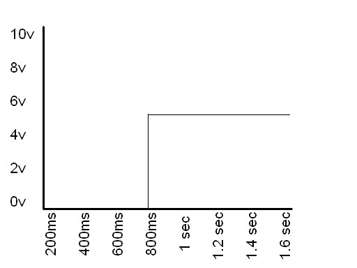 Draw the pattern
ABS Relays


Looking at the wiring diagram, Record the name of the relay or switch that powers up the ABS ECU:
S-13
Record the name of the relay or switch that powers up the ABS pump:
K-100
Record the name of the relay or switch that sends power to the ABS HCU solenoids
K-38
Relay wire identification:
Ws/Rt
What is the ECU pin number for the wire that brings in the power to the ABS ECU?
Pin 1
What is the ECU pin number , or other number, for the wire that controls the relay for the ABS ECU?
Pin 27
What is the pin number for the wire that brings in the power to the ABS pump?
Pin 14
What is the pin number, or other number, for the wire that controls the relay for the ABS pump?
Pin 28
ABS Demonstrators
Using the wiring diagram for your vehicle, find the ABS wheel speed sensor pin out connections to the ECU on the wiring diagram and the demonstrator. Record which ECU wires go to which speed sensors.

Which wheel is this?
 Which wheel is this?
Right Front

Mazda 323 JM BA
Left Front ECU pin# 2O and 2P
Left Rear ECU pin# 2R and 2Q
Right Front ECU pin# 2N and 2M
Right Rear ECU pin# 2S and 2T
By looking at the wiring diagram, what type of speed sensor is this?
Inductive. 4 Channel/ Each wheel has it's own individual sensor. And each sensor only has 2 wires.
Describe how it works
The wheel sensor is placed approximately 1mm above a sensor rotor. As the wheel rotates the pulse ring rotates with it. As each pulse ring passes under the sensor, a small voltage pulse is induced in the sensor. The pulses are sent as input signals to ECU. (ref Ed May and Les Simpson Automotive Mechanics Volume 2)
Locate an oscilloscope. Turn it on and set it up to be fully operational. What oscilloscope are you using.
DIGITECH Dual-Channel Oscilloscope QC1992
Record a Waveform for each wheel speed sensor in the boxes below. Note voltage per division and time for per division for each. Please don't keep the ABS units on very long because it drains the batteries. All Graphs will be in 5V per division on the Y-Axis, and .2 ms on the X-Axis.
Which wheel is this?

Left Front
Which wheel is this?

Left Rear
Which wheel is this?Right Front
Which wheel is this?

Right Rear
Are all the waveforms exactly the same? Yes/ No. Discuss what are the differences, and what can cause the differences between the waveforms.
Are all the waveforms exactly the same? Yes/ No. Discuss what are the differences, and what can cause the differences between the waveforms.
No, the front and rear sensor waveforms were different. The front left and right sensors gave me a amplitude reading of .6V whilst the rear left and right sensors were .4V, but the frequency for all sensors were both .38ms. I first thought they could be different because they had different numbers of teeth for the front and rear rotor teeth. So I checked, but both rotors had 44 teeth. I then measured the resistance for each wheel sensor and recorded .430k for the front wheels and .890k for the rear. I then asked myself how the amplitude could increase with the frequency remaining the same. I checked the air gap of all sensors and they were all within specifications. With all my results from my tests I had to conclude the greater resistance in the rear wheels was why the amplitude was greater for the front wheels, considering the wheels were rotating at the exact same speed.
With the wheel speed sensors spinning, measure AC volts with a multimeter and record here.
Left Front:
3.17V
Left Rear:
Left Rear:
2.68V
Right Front:
Right Front:
4.22V
Right Rear:
Right Rear:
2.85V
Can a multimeter be as accurate as in finding problems with the wheel speed sensors as an oscilloscope? Yes/ No
Can a multimeter be as accurate as in finding problems with the wheel speed sensors as an oscilloscope? Yes/ No
No
Discuss what the oscilloscope could find that the multimeter could not find and why.
The oscilloscope can give you a visual reading of what the sensor is picking up. If there is a chip or dent on the rotor tooth, the oscilloscope will display a break or distorted line indicating where the fault is. An oscilloscope also can measure frequency and amplitude at the same time, while on a multimeter you have to record your result and then change settings to record something else.
ABS Wheel Sensors
 There are 3 main types of Wheel Sensors on modern vehicles. One sends an analogue signal using an inductive pick up, the others send a digital signal using either a hall effect or magneto resistance encoder.
Draw a digital signal that switches 5 Volts every 2 Seconds.
(Left Image)
Draw an analogue signal with a frequency of 0.5 Hz and a maximum of +3 volts. (Right Image)
Note
All Graphs were created using Microsoft Paint and are all my own work
Subscribe to:
Posts (Atom)