Which scan tool are you using: Hanatech Multiscan

Which vehicle are you using: Mitsubishi Galant 1996
With the vehicle safely on jack stands or a lift (use the proper worksheet for that) safely drive the vehicle to allow it to shift up and down through the gears. View the solenoids as the vehicle shifts up and down. Record which solenoids are on in which gears.
With the shift lever in Drive or Overdrive:
First gear solenoids: 2nd/OD
Second gear solenoids: LR/OD
Third gear solenoids: 2nd/LR
Fourth gear solenoids: LR/UN
View the Torque Converter Clutch as you safely drive the vehicle. Record when it is on or off:
Torque Converter Clutch On:
The duty cycle of the torque converter clutch didn't come on until 1400 rpm had been reached in 3rd gear.
Torque Converter Clutch Off:
The duty cycle remained off from start up to 1400 rpm in 3rd gear.
What effect does the brake pedal have on the Torque Converter Clutch Operation?
When we applied the brake pedal, the slip rpm went from 33rpm to 240rpm
Create a shift chart for your vehicle.
Based on the operation of shifting above, create a shift chart that describes what solenoids are on in which gear: 


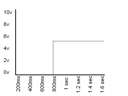
 Capture a waveform that shows both the control circuit change when it turns on the relay, and the power switching on to power something in the ABS system. (Use an oscilloscope with 2 channels to capture this pattern. You may have to carefully set the trigger to capture this.)


 Which wheel is this?


