
Sunday, September 19, 2010
Tuesday, September 7, 2010
Scan Tools
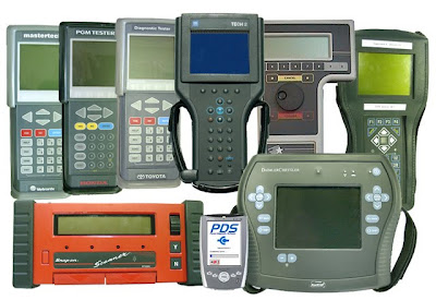
Scan Tools are used to measure and diagnose your vehicle information, such as RPM, Ignition Timing, Injector Pulse width and readings from a number of sensors such as the 02 sensor, TPS (throttle positioning sensor), and (MAF) mass airflow sensor. It will also show certain switch position signals.
 Using A Scan Tool
 Using A Scan Tool
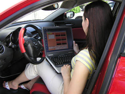
1. Plug the scan tool into the ECU, either under the dash or under the steering wheel. (Could be hidden)
2. Power On the Scan Tool. The display will come on, and after it communicates with the car's computer for a few seconds, it will display an OK message or a menu.
3. Navigate the menu to find the stored codes that the car's computer has stored into memory. These codes are collected overtime, and unless the vehicles battery has been disconnected, they should remain in memory. The scan tool will display these codes, along with basic data information about the code.
4. Write down the codes that are displayed and then research them. Automotive repair manuals will have a list of these codes and what they mean for that type of make or model. Many codes will start with a letter, followed by several numbers, such as F-233, and they are tripped by sensors that the computer monitors constantly. When these sensors determine something is wrong with the motor, they store the code in the computer so that the mechanic can determine the i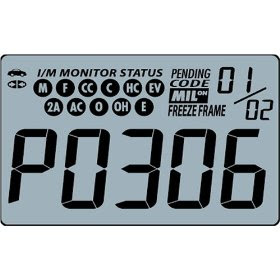 ssue and repair it.
 ssue and repair it.
Example.
Here is a fault code for a 6 cylinder engine.
As you can see this is a 5 digit number, with a letter at the front. When I read the manual for this type of this vehicle, or go to the following website http://www.youfixcars.com/, I can see that the fault code is P0306- Cylinder 6 Misfire Detected. We now know that the 6th cylinder has a fault, and can now try to work out what the actual problem is. It could be a dirty spark plug, dirty distributor or any number of things. But at least now we know what the problem is. However the Scan Tool is preset to finding more priority faults first, so after the problem has been fixed, another isolated problem may still need to be attended to.
Monday, September 6, 2010
Scan Tool Observations
Find a Vehicle that will show you CAN system operation on a scan tool (such as the Range Rover)
Which Vehicle Are you using? Land Rover
Which Scan Tool are you using? Auto Boss
2.2 What different functions are available on the scan tool to examine the CAN system?
Primary Ignition, secondary Ignition, Multimeter, DSO, Engine Analyser
2.3 List the different systems that are controlled by CAN? (note which are high speed and which are low speed)
High
ABS/ TCS/ Engine Control/ EPS
Low
Tv, Windows, Body Control
CAN Multiplexing worksheet
CAN Waveform on an oscilloscope
Colour of wire: Yellow

1.1 Locate the Range Rover or other suitable vehicle with easily accessible CAN system twisted wires. Which vehicle do you have? (Year, Make, Model)
2001 Landrover
1.2 Locate a twisted wire pair. Describe where the wires are located. The Twisted Wire Pair were located inside the engine bay on the Hydraulic Control Unit
1.3 Record the waveform of one of the wires below. ("make sure your time is small enough so you dont have aliasing")
Colour of wire: Yellow
Time per division: 2 Seconds
Voltage per division: 0.5V

1.4 Record the waveform of the other wire.
Colour of wire: Black
Time Per Division: 20ms
Voltage per division: 1V
1.5 What is aliasing? Describe it: When a digital image is viewed, a reconstruction-also known as an interpolation-is performed by a display, and by the eyes and the brain. If the resolution is too low, the reconstructed image will differ from the original image, and an alias is seen. Aliasing can be caused either by the sampling stage or the reconstruction stage; these may be distinguished by calling sampling aliasing prealiasing and reconstruction aliasing postaliasing
1.6 How do you know these waveforms are not alisaling?
Because they are symmetrical when placed together, and this is what it should like.
1.7 In the 1.3 Waveform above, what is the main voltage on the line? 2.5V
What is the other voltage on the line, when the voltage is pulled up or down to "talk"?
1.8 In the 1.4 Waveform above, what is the main voltage on the line? 1.5V
What is the voltage on the line, when the voltage is pulled up or down to "talk"?
1.9 Observe the signals in 1.3 and 1.4 with a voltmeter. Compare it with DC volts or AC volts setting . Which setting would tell you if the signal is switching. Explain. DC Would tell me if the signal is switching because I would get a straight line when it is either on, or off, while analogue will give me a curvy line.
Monday, August 23, 2010
On Car Exercises
Connect a Scan Tool to the vehicle you are testing and bring up the transmission information.
Which scan tool are you using: Hanatech Multiscan

Which vehicle are you using: Mitsubishi Galant 1996
With the vehicle safely on jack stands or a lift (use the proper worksheet for that) safely drive the vehicle to allow it to shift up and down through the gears. View the solenoids as the vehicle shifts up and down. Record which solenoids are on in which gears.
With the shift lever in Drive or Overdrive:
First gear solenoids: 2nd/OD
Second gear solenoids: LR/OD
Third gear solenoids: 2nd/LR
Fourth gear solenoids: LR/UN
View the Torque Converter Clutch as you safely drive the vehicle. Record when it is on or off:
Torque Converter Clutch On:
The duty cycle of the torque converter clutch didn't come on until 1400 rpm had been reached in 3rd gear.
Torque Converter Clutch Off:
The duty cycle remained off from start up to 1400 rpm in 3rd gear.
What effect does the brake pedal have on the Torque Converter Clutch Operation?
When we applied the brake pedal, the slip rpm went from 33rpm to 240rpm
Create a shift chart for your vehicle.
Based on the operation of shifting above, create a shift chart that describes what solenoids are on in which gear: 
Codes and diagnostics
Codes:
Pick two transmission codes out of repair information, and describe what the code means and what mailfunction would cause the code:
Code: LR Solenoid Valve Open
Code:OD Solenoid Valve Open
Diagnosis:
For each code listed above, discuss what tests you could run to diagnose the problem.
1st problem testing:
With the vehicle stuck in 3rd gear, we tryed shifting the car into a different gear. But because all the solenoid valves were stuck open and wouldn't close, the vehicle would not shift and it stayed in 3rd gear.
2nd problem testing
For the 2nd test, we plugged the solenoid cable back into the transmission and turned the car on. We were then able to change up and down gears. We then used the scan tools to make sure the valves were closing when we changed gears and they did.
Shift Solenoids
Use the following Holden Shift chart for questions below.

Shift Solenoids
Which solenoids are "on" when this vehicle is shifted into drive and starts out in first gear?
Both Solenoids are on on when this vehicle is in 1st gear.
Which solenoids are "on" when this vehicle automatically shifts into second gear?
When the vehicle switches to second gear, the second solenoid is on
Which solenoids are "on" when this vehicle automatically shifts into third gear?
No solenoids are on when this vehicle is in 3rd gear
Which solenoids are "on" when this vehicle automatically shifts into fourth gear?
The 1st solenoid is on when this vehicle is in 4th gear
Shift solenoid mailfunction
Describe what would happen if none of these solenoids came "on". Could the vehicle drive? What gear would it be in? How fast could it go? Could it have the power to climb a hill?
If all the solenoids were off in this vehicle, the only gears this vehicle could use would be 3rd gear. That is because in 3rd gear this transmission does not need any solenoids on. The vehicle will be slow and sluggish at start off and could only use third gear. As for climbing a hill, the vehicle could drive up it if the vehicle had a running start.
Subscribe to:
Comments (Atom)